Arduino Uno Wifi Wireless Upload Sketch Esp8266
A fantastic feature of any WiFi-enabled microcontroller like ESP8266 NodeMCU is the ability to update its firmware wirelessly. This is known as Over-The-Air (OTA) programming.
What is OTA programming in ESP8266?
The OTA programming allows updating/uploading a new program to ESP8266 using Wi-Fi instead of requiring the user to connect the ESP8266 to a computer via USB to perform the update.
OTA functionality is extremely useful in case of no physical access to the ESP module. It helps reduce the amount of fourth dimension spent for updating each ESP module at the time of maintenance.
Ane important characteristic of OTA is that i central location can send an update to multiple ESPs sharing same network.
The only disadvantage is that y'all have to add an extra code for OTA with every sketch you upload, so that you lot're able to use OTA in the next update.
3 Unproblematic Steps To Use OTA with ESP8266
- Install Python 2.7.ten seriesThe get-go footstep is to install Python 2.7.x serial in your computer.
- Upload Basic OTA Firmware SeriallyUpload the sketch containing OTA firmware serially. It'due south a mandatory step, so that you're able to practice the side by side updates/uploads over-the-air.
- Upload New Sketch Over-The-AirNow, y'all tin can upload new sketches to the ESP8266 from Arduino IDE over-the-air.
Pace ane: Install Python 2.7.ten serial
In order to utilize OTA functionality, y'all need to install the Python 2.7.ten version, if not already installed on your machine.
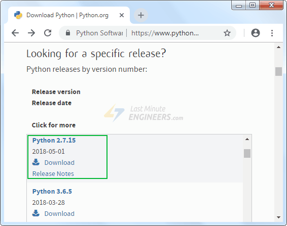
Go to Python'southward official website and download 2.7.10 (specific release) for Windows (MSI installer)
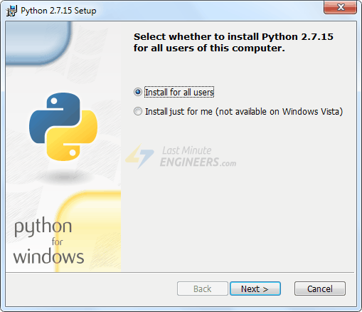
Open the installer and follow the installation wizard.
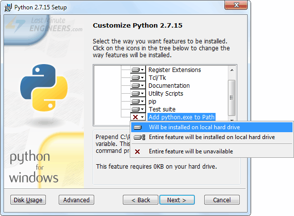
In Customize Python two.7.Ten section, brand sure the last option Add together python.exe to Path is enabled.
Footstep 2: Upload OTA Routine Serially
The factory image in ESP8266 doesn't accept an OTA Upgrade capability. So, you demand to load the OTA firmware on the ESP8266 through series interface starting time.
It'south a mandatory step to initially update the firmware, so that yous're able to do the adjacent updates/uploads over-the-air.
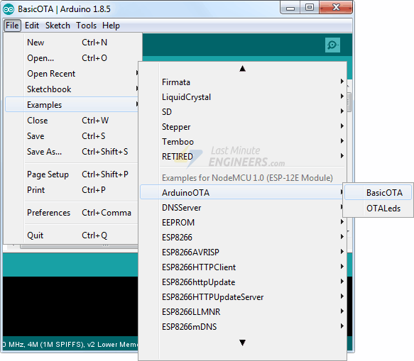
The ESP8266 addition for the Arduino IDE comes with a OTA library & BasicOTA example. Yous can access it through File > Examples > ArduinoOTA > BasicOTA.
The following code should load. But, before yous head for uploading the sketch, yous need to make some changes to make it piece of work for you. You need to modify the following two variables with your network credentials, and then that ESP8266 can establish a connection with existing network.
const char* ssid = ".........."; const char* password = ".........."; In one case you are done, go ahead and upload the sketch.
#include <ESP8266WiFi.h> #include <ESP8266mDNS.h> #include <WiFiUdp.h> #include <ArduinoOTA.h> const char* ssid = ".........."; const char* password = ".........."; void setup() { Serial.begin(115200); Serial.println("Booting"); WiFi.mode(WIFI_STA); WiFi.begin(ssid, password); while (WiFi.waitForConnectResult() != WL_CONNECTED) { Serial.println("Connection Failed! Rebooting..."); delay(5000); ESP.restart(); } // Port defaults to 8266 // ArduinoOTA.setPort(8266); // Hostname defaults to esp8266-[ChipID] // ArduinoOTA.setHostname("myesp8266"); // No hallmark by default // ArduinoOTA.setPassword("admin"); // Password can be set with it'south md5 value besides // MD5(admin) = 21232f297a57a5a743894a0e4a801fc3 // ArduinoOTA.setPasswordHash("21232f297a57a5a743894a0e4a801fc3"); ArduinoOTA.onStart([]() { String type; if (ArduinoOTA.getCommand() == U_FLASH) type = "sketch"; else // U_SPIFFS blazon = "filesystem"; // Note: if updating SPIFFS this would be the place to unmount SPIFFS using SPIFFS.end() Series.println("Start updating " + type); }); ArduinoOTA.onEnd([]() { Serial.println("\nEnd"); }); ArduinoOTA.onProgress([](unsigned int progress, unsigned int full) { Serial.printf("Progress: %u%%\r", (progress / (total / 100))); }); ArduinoOTA.onError([](ota_error_t error) { Series.printf("Error[%u]: ", error); if (error == OTA_AUTH_ERROR) Serial.println("Auth Failed"); else if (error == OTA_BEGIN_ERROR) Series.println("Brainstorm Failed"); else if (error == OTA_CONNECT_ERROR) Serial.println("Connect Failed"); else if (error == OTA_RECEIVE_ERROR) Serial.println("Receive Failed"); else if (fault == OTA_END_ERROR) Serial.println("End Failed"); }); ArduinoOTA.begin(); Serial.println("Gear up"); Series.print("IP address: "); Serial.println(WiFi.localIP()); } void loop() { ArduinoOTA.handle(); } Now, open up the Serial Monitor at a baud rate of 115200. And printing the RST button on ESP8266. If everything is OK, information technology will output the dynamic IP address obtained from your router. Notation it down.

Step iii: Upload New Sketch Over-The-Air
Now, permit's upload a new sketch over-the-air.
Remember! you need to add together the code for OTA in every sketch you upload. Otherwise, you'll loose OTA capability and will not be able to do side by side uploads over-the-air. So, it'due south recommended to modify the above code to include your new code.
Every bit an example nosotros will include a elementary Blink sketch in the Bones OTA lawmaking. Recollect to modify the SSID and countersign variables with your network credentials.
Changes in the Basic OTA program are highlighted in Blue.
#include <ESP8266WiFi.h> #include <ESP8266mDNS.h> #include <WiFiUdp.h> #include <ArduinoOTA.h> const char* ssid = ".........."; const char* password = ".........."; //variabls for blinking an LED with Millis const int led = D0; // ESP8266 Pin to which onboard LED is connected unsigned long previousMillis = 0; // will shop final fourth dimension LED was updated const long interval = 1000; // interval at which to blink (milliseconds) int ledState = LOW; // ledState used to set the LED void setup() { pinMode(led, OUTPUT); Series.begin(115200); Serial.println("Booting"); WiFi.mode(WIFI_STA); WiFi.brainstorm(ssid, countersign); while (WiFi.waitForConnectResult() != WL_CONNECTED) { Serial.println("Connection Failed! Rebooting..."); delay(5000); ESP.restart(); } // Port defaults to 8266 // ArduinoOTA.setPort(8266); // Hostname defaults to esp8266-[ChipID] // ArduinoOTA.setHostname("myesp8266"); // No authentication by default // ArduinoOTA.setPassword("admin"); // Password tin exist set with information technology'due south md5 value as well // MD5(admin) = 21232f297a57a5a743894a0e4a801fc3 // ArduinoOTA.setPasswordHash("21232f297a57a5a743894a0e4a801fc3"); ArduinoOTA.onStart([]() { String blazon; if (ArduinoOTA.getCommand() == U_FLASH) blazon = "sketch"; else // U_SPIFFS type = "filesystem"; // NOTE: if updating SPIFFS this would be the place to unmount SPIFFS using SPIFFS.end() Series.println("First updating " + type); }); ArduinoOTA.onEnd([]() { Series.println("\nEnd"); }); ArduinoOTA.onProgress([](unsigned int progress, unsigned int total) { Serial.printf("Progress: %u%%\r", (progress / (total / 100))); }); ArduinoOTA.onError([](ota_error_t mistake) { Serial.printf("Error[%u]: ", error); if (mistake == OTA_AUTH_ERROR) Serial.println("Auth Failed"); else if (error == OTA_BEGIN_ERROR) Series.println("Begin Failed"); else if (error == OTA_CONNECT_ERROR) Serial.println("Connect Failed"); else if (error == OTA_RECEIVE_ERROR) Serial.println("Receive Failed"); else if (error == OTA_END_ERROR) Serial.println("End Failed"); }); ArduinoOTA.begin(); Serial.println("Ready"); Serial.impress("IP address: "); Serial.println(WiFi.localIP()); } void loop() { ArduinoOTA.handle(); //loop to blink without delay unsigned long currentMillis = millis(); if (currentMillis - previousMillis >= interval) { // save the concluding fourth dimension y'all blinked the LED previousMillis = currentMillis; // if the LED is off turn information technology on and vice-versa: ledState = not(ledState); // prepare the LED with the ledState of the variable: digitalWrite(led, ledState); } } In above plan, we have not used delay() for blinking an LED, because ESP8266 pauses your programme during the delay(). If next OTA request is generated while Arduino is paused waiting for the delay() to pass, your program will miss that request.
Once you copy higher up sketch to your Arduino IDE, become to Tools > Port option and y'all should meet something like this: esp8266-xxxxxx at your_esp_ip_address If you lot can't observe it, yous may demand to restart your IDE.
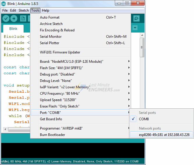
Select the port and click Upload button. Inside a few seconds, the new sketch will be uploaded. And you should see the on-board LED blinking.
kirkhamthavinct54.blogspot.com
Source: https://lastminuteengineers.com/esp8266-ota-updates-arduino-ide/
0 Response to "Arduino Uno Wifi Wireless Upload Sketch Esp8266"
Enregistrer un commentaire